Process Optimization
How to Reliably Create Features of a Specific Depth
The quick, flashy answer:
Easily with MicroBlasting! (Cue cheers, applause, and confetti cannons!)
The long R&D answer:
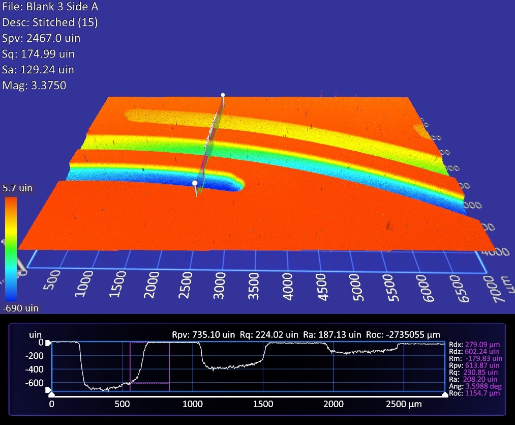
A single pass of the focused abrasive stream from a MicroBlaster can uniformly remove 5 µin (0.127 microns) or less of material depending on the substrate, abrasive, and blast parameters. Given this level of precise and controllable erosion, you simply need to know how to fine-tune the process to suit your application. MicroBlasting is so controllable, you can even create features with varying depths and sharp walls like on the surface depicted below. (Cue supporting details, more images, concrete examples and helpful suggestions!)
Working with hydrodynamic Seals? microFluidics? Semiconductors?
Then, you know the challenge of milling, cutting or etching features a few microns to a millimeter deep into your part’s surface. It’s a tricky, precise and delicate process often made trickier by the large volume of parts that must be processed. Before we look at these individual applications, let’s address a few micro-abrasive blasting basics:
First and Foremost
MicroBasting is ideal for these applications because:
- it provides fully automated control.
- it is heat-less, shock-less and vibration-less.
- it is easy to clean-up.
4 Variables to Consider
To determine how much material can be removed in a single pass, consider:
- Abrasive Type (shape, size, and composition) – The size, shape, and hardness of the abrasive impacts how much energy is transferred to the substrate resulting in erosion.
- Abrasive Velocity (controlled by pressure, blaster configuration and nozzle distance) – The kinetic energy of the abrasive affects how deeply the particles cut into a surface and remove material.
- Abrasive Quantity (controlled by blaster configuration and blast duration) – The amount of abrasive each unit area of the substrate receives over a given time measured in grams per cm² per second.
- Substrate Properties (hardness, crystal structure or grain size, ductility, homogeneity,etc.) – The sum of all the chemical, physical and mechanical properties of the targeted part that affect how easily material is removed from the part during the erosion process.
Abrasives: Find Your Type
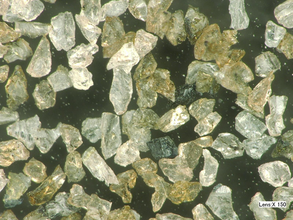
The first choice to make in any controlled erosion process is what abrasive type to use. Controlled erosion applications almost always use “cutting” abrasives. One of the most common abrasives used in controlled erosion applications is 17.5 µ aluminum oxide, which yields a Ra surface finish of 0.15-0.3µm (6-12 µin).
Some applications use silicon carbide, which is harder than aluminum oxide and thus causes more erosion under the exact same conditions. Silicon carbide removes more material with each pass, but it is less controllable−like using a big shovel, where a little shovel works better.
Removal rates are affected as much by abrasive particle size as by abrasive type. The advantage of a large particle size is that more material erodes in less time using less powder. The disadvantage is that it provides less depth control, increased surface roughness, and messier transitions between eroded and untouched areas. So, if your specifications aren’t too critical (example: 1000 micron depth +- 150 microns); a large particle size could work fine for your application.
Velocity: More Than Just Turning the Dial
Typical particle velocities during controlled erosion applications are 150-225 m/s (492-739 ft/s), based on air pressure, nozzle geometry and blast distance from the nozzle to the part.
Velocity is controlled by the nozzle size, blast pressure, and distance from nozzle to target. We’ve talked about velocity to a degree in this post on blast pressure and this post on nozzle distance. We keep touching on velocity because it has a huge impact on most applications; particularly, controlled erosion applications.
The simplest way to speed up your erosion process is to dial up the pressure. Again, that could result in less precise depth control, which leads to greater unevenness in the final surface. Worse, you could potentially destroy the mask before the erosion is even complete. (This is more likely to occur with photo-resist masks and other plastic masking materials).


Nozzle Position: Keep it Straight
Point the nozzle tip straight down at the target.* As in, perpendicular. If the part curves, the nozzle should follow the curve so that it remains perpendicular to the target. If the nozzle ends up at an angle−however slight−to the target; the erosion rate will drop; walls on either side of the channel will form different slopes, and masking may get undercut.
*There are rare exceptions to this rule, but they are too rare to bother diving into them.
Distance from Nozzle to Target
Most masked or blanket erosion is done at a nozzle distance of 1.5″ to 2″ from the part. Long working distances have two distinct advantages:
- Powder distribution across the spot diameter is more uniform.
- Spot size is larger than the desired features.
Long working distances provide better erosion control and less depth variation across the part than close nozzle distances. Again, once you select the nozzle-to-part distance, that distance must be maintained over the entire part. If not, variations in the particle velocity and quantity (amount per unit area) occur, causing uneven erosion and possibly ruining the part.
Quantity: Fast and Lean
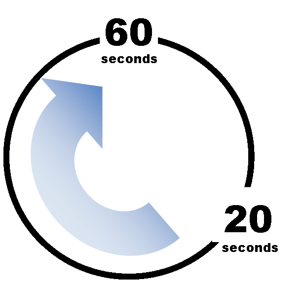
MicroBlasting usually takes 20-60 seconds per square inch of material blasted per pass. Most applications benefit from running the nozzle as fast as possible. Doing so:
- preserves/limits damage to masking material.
- provides better depth control per pass.
Controlled erosion applications tend to run a lean abrasive flow, which is less than 10 grams per minute. At a certain depth, abrasive particles begin hitting one another rather than the substrate material. Basically, the particles leading the charge cannot get out of the way quickly enough for those following behind.
Substrate Materials: Brittle vs. Ductile
(Spoiler: Brittle is best!)
The shockless nature of MicroBlasting is well-suited for machining very hard, brittle materials, including but not limited to:
- silicon
- quartz
- sapphire
- glass
- ceramics
- graphite
- composites
- hardened steel
Brittle materials tend to erode quickly as nearly all of the deposited abrasive energy goes into breaking the material bonds holding the surface together.
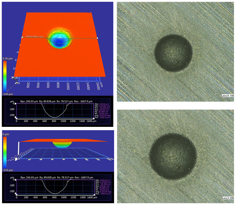
Ductile material absorbs and deflects abrasive energy thanks to its natural elasticity. Thus, ductile parts erode slower than brittle parts with similar hardness. The resulting finish on a ductile material is rougher than on a brittle material because the impact of the abrasive causes the edges of each surface crater to smoosh upward.
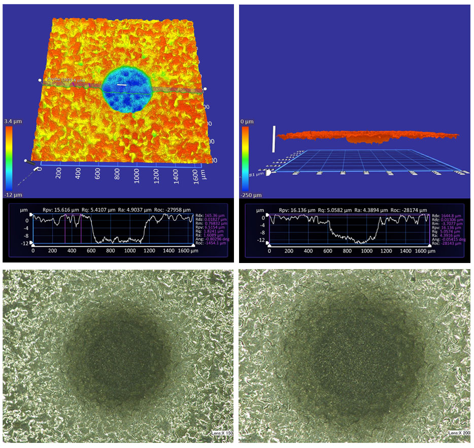
The characteristics of the substrate material also impact surface roughness. The finer the grain structure and the fracture mechanics of the substrate; the lower the Ra after blasting.
Important Note!
MicroBlasting is most effective on homogeneous materials. Pitting is likely to occur on sintered parts.
The Tools Needed
The distinction of using MicroBlasting is the ability to feed fine abrasives (10-100 µm / 0.0004-0.0040″) and to control abrasive output (1-50 grams / 0.035-1.76 oz per minute) even using automated systems. Most controlled erosion applications require processing a high volume of parts, which automated systems tend to handle more efficiently than a team of highly skilled technicians. These applications also benefit from masking and programming which automation provides.
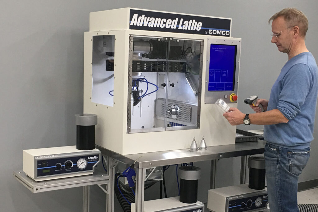
The Advanced Lathe
Comco provides two options for automated systems designed for production environments: the LA3250 or Advanced Lathe, and the LA4250, or JetCenter (new!). The Advanced Lathe is ideal for most small and cylindrical parts. It provides single-part loading, batch processing and can process multiples sides and regions on a part thanks to its rotating spindle.
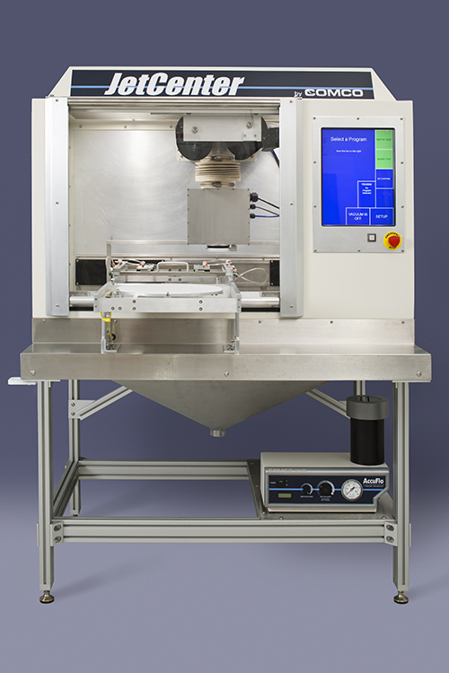
THE JETCENTER
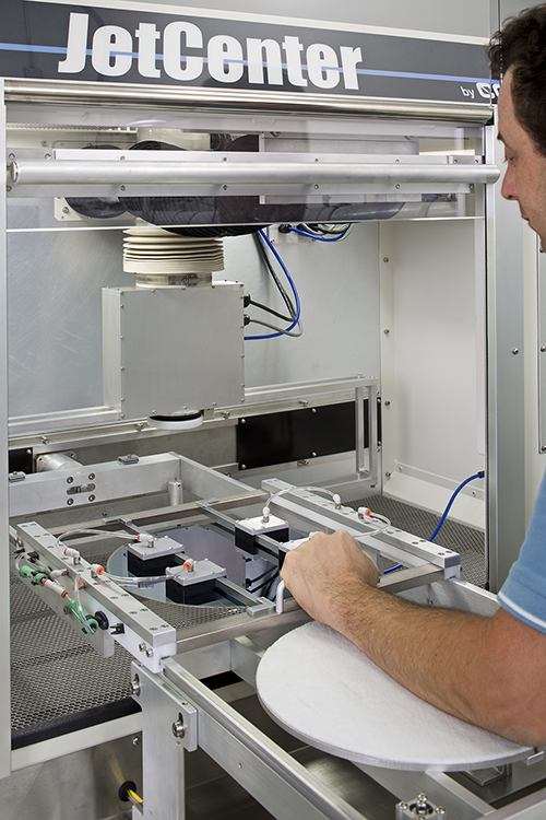
The JetCenter, our latest automation system, is ideal for large and flat parts and generally, larger batches of parts. The JetCenter features a flexible blast head that allows its nozzles to better follow the contour of a part. It is best, too, for parts that require additional automation.
Hydrodynamic Seals
MicroBlasting is used to carve channels into hydrodynamic seals. These channels are usually 0.04″ wide. At a nozzle distance of 1.5″, a 0.060″ Comco Hi/Performance nozzle (MB2520-60) creates a spot that is 0.36″ in diameter—nearly 10x the feature size. Thus, the abrasive stream is nearly uniform across the part as the nozzle travels across the channel. The result is a nice, flat bottom of the channel.
If the nozzle is closer than 1.5″, then the spot size may be double or triple the channel width. The middle of the channel may erode faster than the edges due to higher powder densities in the middle of the blast, giving the channel a rounded bottom and shallower walls.

MicroFluidics
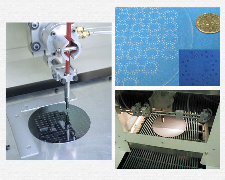
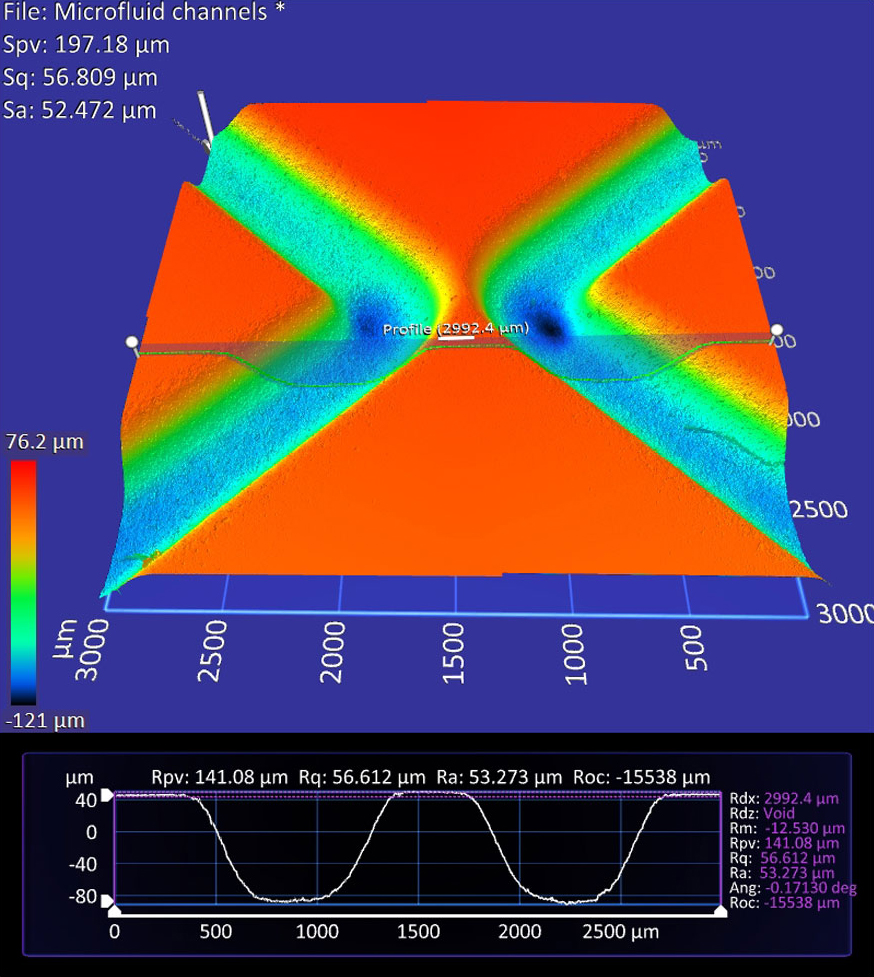
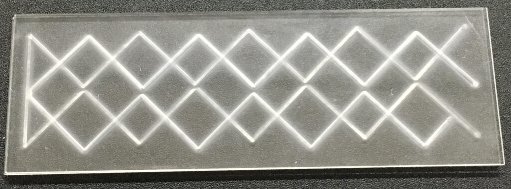
In the application pictured here, our customer used MicroBlasting to cut two microchannels into the top and bottom glass slides on a blood mixer. This particular design allows fluids to properly mix at channel intersections.
The channels were cut with a 0.030″ Comco Hi/Performance (MB2520-30 nozzle) blasting 17.5 aluminum oxide at 50 PSI. The nozzle distance was close (0.05″ from the target) in order to cut a trough with relatively steep sides without using masking. This is one of the few applications where an extremely close nozzle distance is necessary.
Semiconductors
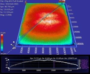
The application pictured in the optical image below required the removal of over 700 microns of silicon while preserving the curved profile of the part and leaving a 50 µ layer of protection over the transistors and electronics.
Comco’s Advanced Lathe processed the part, using a 0.046″ Comco Hi/Performance (MB2520-46) nozzle at 1.625″ from the part, blasting 17.5 µ aluminum oxide at a blast pressure of 40 PSI. The lathe spun the part at 300 RPM, moving the nozzle radially in and out along the part. The lathe was programmed to adjust the nozzle’s radial speed to maintain uniformity of removal.
Bringing it All Together
Like any good team, these variables work together to make their magic. And so, tweaking one affects another.
The Key Relationships to Remember:
- Turning up the pressure increases particle velocity, which gives abrasive more energy to remove material. It also increases the abrasive quantity, compounding the rate of material removal.
- Moving the nozzle closer to the part concentrates the abrasive to a smaller area, but reduces abrasive velocity. At this point, particles lack enough distance to accelerate to maximum speed.
- Switching nozzles in order to alter spot size will change the mass flow rate and the stream velocity.
