Process Optimization
How to Calculate Stepover and Get a Uniform Finish
“Where did these stripes come from?”
This is a question we hear in automated texturing and etching applications. Most customers want to avoid creating a barber-pole or stripe pattern on their part surface. Aesthetic reasons aside, uneven part finishes severely impact bond adhesion, osseointegration, and general part performance. The answer is pretty simple. Through testing, we have found a 20% stepover yields a uniform surface finish in most applications.
Let’s dig into why…
What is Spot Size
efore we dive into stepover calculations, let’s define “spot size.” Spot size is the affected region or the pattern that the blast stream etches on a targeted surface. The affected region does not include overspray. Overspray has no meaningful impact; rather, it is just a “frosting” on the surface.
Two factors determine spot size:
- the size of the nozzle opening
- the distance between the tip of the nozzle and the targeted surface
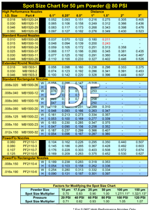
The chart to the left provides estimated spot sizes for Comco nozzles. The post on the right below dives deep into spot size in case you would like more context.
Calculating Stepover for Cylindrical Parts
General Rule: move the nozzle 20% or 1/5th of the spot size per revolution when blasting cylindrical parts.
For example, if the spot size has a 1″ diameter, the nozzle should move position by 0.2″ after each pass. That means that the nozzle would move a total of 1″ in 5 passes.
First, calculate spot size to get the step size. Before the rotational speed and the nozzle speed can be calculated, the stepover distance must be identified. To identify the stepover distance (step size), you need to know the spot size.
Refer to the spot size chart above, then use the Spot & Step Size Calculator below OR the following equation:
Distance per revolution (d) = spot size ⁄ 5
Then, If you know the spindle speed…
If you have already programmed a spindle speed, then calculate the nozzle speed using the Nozzle Speed Calculator below OR this equation:
V=d*RPM ⁄ 60 (RPM= revolutions per minute or spindle speed)
Where (V) in the equation above is your upper limit for nozzle speed. Going slower is okay, but going faster risks creating a barber pole pattern.
Or, if you know the nozzle speed…
Conversely, if you know the nozzle speed (V), you can calculate the recommended spindle speed (RPM) using the Spindle Speed Calculator below OR this equation:
RPM= 60*V ⁄ d
Stepover examples
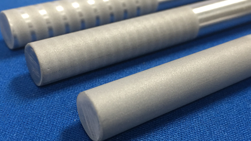
We processed 3 samples to illustrate the importance of sticking to the 1/5th or 20% stepover rule.
Determining Stepover for Flat Surfaces
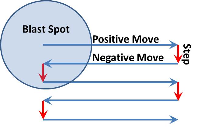
The blast pattern is relatively easy to calculate for a flat surface. After determining the spot size, a serpentine pattern can be quickly programmed into the automated system. The Spot and Step Size Calculator above is appropriate for these applications, too. And that’s it. The key is knowing the spot size and sticking to the 20% rule.
About Automation
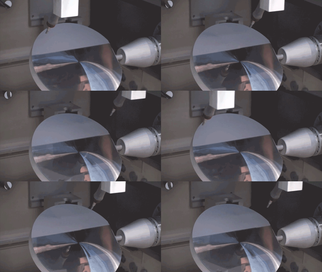
To get the amount of control needed to produce repeatable surface finishes, you probably need to automate. Both of Comco’s systems, the Advanced Lathe and the JetCenter, provide careful control over particle velocity and coverage, that help create consistently uniform surfaces. Comco automated systems can create surfaces as smooth as 10 µin or as rough as 200 µin.
Some benefits of Comco automated systems:
- Built from a proven platform
- Easily programmed and configured for specific applications
- Offered as a turnkey solution, including tooling, blast head, and programming development
- Multiple blaster options (though AccuFlo suits this application best)
- An easy-to-read touch screen display
- Network compatible
